Home > Industry Solutions > Preventing and Resolving Chipping in QFN Packaging

04

Nov

Preventing and Resolving Chipping in QFN Packaging

13
Share:

What Is QFN Chipping and Why Does It Matter?

QFN is a leadless package widely used in high-density, high-frequency and power-sensitive semiconductor devices. Because it has no protruding leads, the copper leadframe is exposed at the package edge after singulation. During dicing, defects typically appear in three forms:

EMC chipping / peeling — fracture of the brittle epoxy molding compound along the cut edge.
Copper burrs (flash) — ductile tearing of the copper leadframe that leaves burrs on the side wall.
Substrate delamination — separation at the copper-to-EMC interface.
Any of these defects can expose internal circuitry, reduce solder-joint reliability, and cause devices to fail electrical testing — driving down yield and increasing scrap cost in high-volume packaging lines.
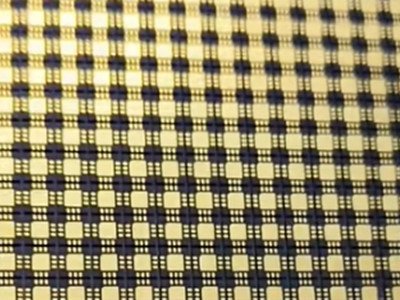
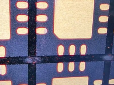
packing substrate Cutting seam

Root‑Causes of Chipping Defects in QFN Dicing

Chipping originates from excessive mechanical impact, thermal stress and unstable cutting conditions at the EMC‑copper boundary. Four dominant contributing factors are summarized below.
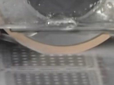
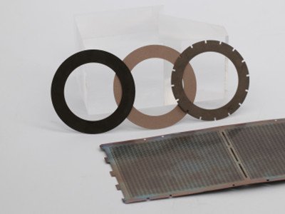
  1. Inappropriate dicing blade selection
    Blades with overly high hardness or poorly‑matched bonding material deliver excessive impact force onto brittle EMC during cutting. Brittle bond systems cannot buffer instantaneous shear stress, initiating micro‑cracks that expand into visible edge chipping.
  2. Non‑optimized cutting parameters
    Excessive feed speed or spindle‑rpm mismatches against diamond grit size introduce heavy lateral tension across the package. High feed‑rate aggravates mechanical tearing at copper‑EMC boundaries, triggering burrs and corner chipping, especially for high‑density QFN devices.
  3. Inadequate cooling and debris evacuation
    Insufficient pure‑water coolant flow results in heat accumulation within the cutting zone. Elevated local temperature softens EMC resin, induces resin smearing, and causes copper debris adhesion onto the dicing blade. Built‑up chips further worsen cutting stability and edge quality.
  4. Blade run‑out and mechanical vibration
    Degraded spindle precision or incorrect blade mounting produces radial and axial run‑out. Periodic lateral shear force from run‑out creates cyclic impact damage, leading to periodic chipping patterns on singulated QFN units.

QNF dicing QFN cuttings

Solution: MORESUPERHARD 1A8 Resin‑Bond Diamond Dicing Blades

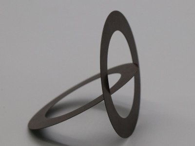
MORESUPERHARD 1A8 series resin‑bond diamond dicing blades are purpose‑engineered for singulation of QFN, DFN, BGA and LGA semiconductor packages. The resin matrix features good elasticity and self‑sharpening capability, which absorbs cutting shock, restrains micro‑crack extension and mitigates chipping, copper burr and delamination risks.

Blade Selection Guidelines

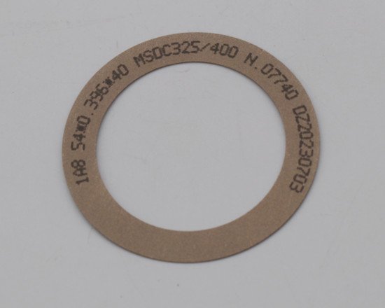
  • Recommended product: MORESUPERHARD 1A8 resin‑bond diamond dicing blade, customizable dimensions e.g. 58 × 0.3 × 40 [adjust per actual drawing]
  • Grit & concentration: Micron‑grade diamond grit such as SD240. Grit specification shall be tuned according to copper leadframe thickness, to minimise mechanical tearing along copper‑EMC interfaces.
  • Applicable copper thickness coverage: up to 150‑200 µm.

resin diamond dicing blades 5 resin diamond dicing blades for QFN

Reference Process Window

Parameter Recommended Setting Remarks
Spindle Speed 20 000‑30 000 rpm Tune according to blade thickness
Feed Rate 30‑70 mm/sec Reduce feed speed for high‑density QFN to lower lateral stress
Coolant (pure water) ≥ 1.5 L/min Guarantee heat dissipation and effective flushing of cutting debris

Advanced Process Improvement Measures

Step‑cut (Dual‑Action) Cutting Process

For QFN devices requiring wettable flank sidewalls, adopt a two‑stage step‑cut workflow. First, perform shallow pre‑cutting on the copper layer using fine‑grit MORESUPERHARD resin‑bond blade; execute full‑depth cutting in the second pass. This strategy disperses concentrated cutting stress and significantly reduces edge chipping risk.

Strict Run‑Out Management

Control spindle radial & axial run‑out within ≤ 25 µm (≤ 0.001 inch). Regular spindle maintenance and standardized blade mounting eliminate vibration‑induced cyclic chipping defects.

Outcomes & Benefits

When MORESUPERHARD 1A8 resin‑bond dicing blades are combined with optimized cutting recipes, step‑cut procedure and tight run‑out control, manufacturers can achieve clean, burr‑free singulation edges. This solution cuts EMC chipping, copper burr and substrate delamination failure rates, lifts production yield, and improves long‑term reliability of QFN semiconductor components.

Serrated diamond dicing blades resin diamond dicing blades for QFN

Frequently Asked Questions

Q1: Why resin‑bond blades perform better for QFN compared with metal‑bond blades?
A1: Resin bond matrix provides elastic cushioning during cutting to absorb shock loads on brittle EMC material. Metal‑bond blades feature higher rigidity yet limited shock‑absorbing capacity, which tends to generate more chipping on moulding compound.
Q2: When should I apply step‑cut process?
A2: Step‑cut is strongly suggested for QFN with wettable‑flank requirements or thick copper leadframe, where single‑pass deep cutting creates high concentrated stress.
Q3: Can high feed‑rate improve throughput without chipping?
A3: Higher feed‑rate boosts throughput but increases lateral shear stress. For high‑density QFN, moderate feed‑rate reduction is necessary to balance throughput and edge quality.

Conclusion

QFN chipping during dicing is a multi‑factor defect originating from blade hardware, cutting parameters, cooling condition and equipment mechanical status. Adopting purpose‑designed resin‑bond diamond dicing blades together with standardized process recipes offers a systematic mitigation path. Semiconductor packaging houses can suppress EMC chipping, copper burrs and delamination, raise manufacturing yield and enhance component reliability for QFN‑family packages.

También podría ser de su interés
dicing ceramic blades

Diamond Dicing Blades For Ceramic Substrates

Ceramic substrate is a sheet material based on electronic ceramics that forms a supporting base for circuit components.Moresuperhard provide quality diamond dicing blades for dicing different ceramic substrates with precision and efficiency.
resin bond diamond dicing blades

Resin Bond Diamond Dicing Blades-hubless type

Resin diamond dicing blade is a sintered scribing blade made of thermosetting resin as a binder and sintered with diamond abrasive. The resin dicing blade has the characteristics of good elasticity, thin thickness and high precision. It is suitable for processing glass, ceramics and magnetic materials. , cemented carbide and various semiconductor packaging materials.
tech@moresuperhard.com
008617700605088