05
Nov
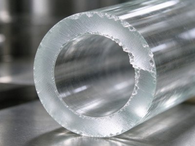
Quartz glass is a typical brittle material with Mohs hardness of 5.5‑6.5 and extremely low fracture toughness. Minor mechanical shock, vibration, thermal stress, or unsupported cutting‑exit surfaces will trigger edge chipping and subsurface micro‑cracks. For automatic cutting of large‑diameter thick‑wall quartz tubes (wall thickness 8‑16 mm), common defects include end‑face chipping, front‑and‑rear material breakout, exit‑edge spalling, and invisible micro‑cracks. These defects lead to mass rejection during subsequent cleaning, heat treatment and assembly, and severely reduce production yield across the quartz‑processing industry. Simply replacing cutting wheels rarely resolves recurring chipping, as defects arise from the combined effects of brittle‑material exit‑effect, vibration, thermal stress and improper cutting logic.
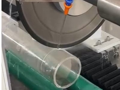
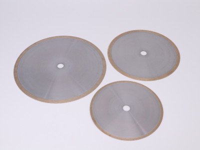
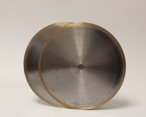
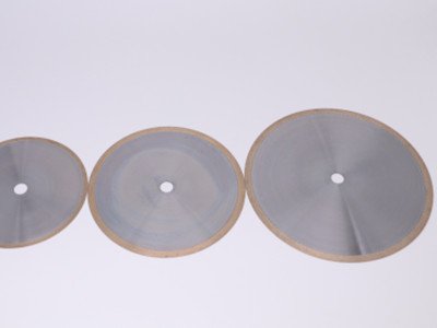
Industry baseline: Electroplated diamond wheels work reliably for thin‑wall tubes below 3 mm wall thickness. For wall thickness ≥8 mm, resin‑bonded diamond wheels represent the mainstream mature solution in domestic optical and semiconductor quartz processing.
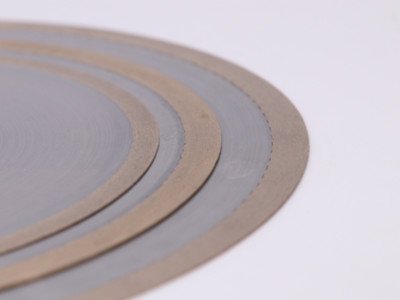
Perimeter ProfileContinuous un‑notched rimReject corrugated or notched segmented rims; intermittent cutting creates periodic mechanical shock and increases chipping probability.
| Parameter Item | Recommended Specification | Notes & Risk of Deviation |
|---|---|---|
| Bond Agent | Resin bond | Provides micro‑elastic cushioning, soft cutting action and restrains crack expansion; avoid metal‑sintered bond for thick‑wall applications. |
| Diamond Grit Size | 240#‑320# | Coarser than 200#: fast cutting yet heavy chipping and rough end face; finer than 400#: high cutting resistance, tool bogging and excessive heat, only for wall <3 mm. |
| Diamond Concentration | 35%‑40% | Excessive concentration causes grain crowding and poor self‑sharpening; low concentration raises single‑grain load and edge hammering. |
| Wheel Thickness | 1.0‑1.4 mm | Ultra‑thin wheels lose rigidity and wobble at 8000 RPM; select thinnest wheel while maintaining sufficient structural stiffness. |
| Diamond Grade | High‑strength monocrystalline diamond with good self‑sharpening performance | Low‑fracture‑toughness fragmented diamond fractures prematurely and shifts material removal into destructive friction‑dominated rubbing. |
| Mounting Flange | Flange parallelism ≤0.005 mm; flange diameter ≥1/3 of wheel outer diameter | Even clamping pressure suppresses high‑speed wheel run‑out. |
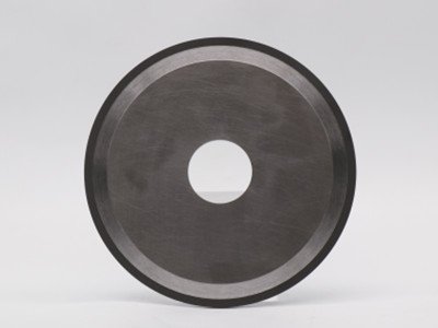
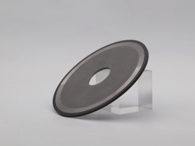
With spindle speed fixed at 8000 RPM, modifying feed strategy delivers fast low‑cost improvement against chipping defects.
Do not cut through the wall using constant‑speed single‑pass feed:
Reference overall feed range for resin‑bond wheels: 30‑60 mm/min. Reduce feed rate when chipping persists before attempting wheel replacement.
Dry cutting generates extreme thermal stress and unavoidable hidden micro‑cracks. Use filtered pure water plus small‑dose neutral rust inhibitor for coolant. Oil‑containing cutting fluids are forbidden as residues penetrate micro‑cracks. Deploy dual‑nozzle layout: one aimed at cutting entry zone, the second directed at the rear exit engagement zone. Coolant must directly impinge the kerf interface and flush quartz dust to prevent secondary scratch damage from trapped swarf.
Resin‑bond wheels develop resin glazing and passivated diamond grains in service. Cutting transitions from abrasive removal to compressive rubbing, which re‑introduces chipping. Dress wheels periodically with white‑alumina dressing blocks to expose fresh sharp diamond abrasive points.
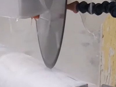
Hollow tubing fundamentally differs from solid rod stock: the rear kerf position is unsupported during penetration.
Adopt fully‑enclosed soft‑gum V‑blocks lined with rubber or polyurethane to distribute clamping force; avoid direct hard‑metal contact with quartz surfaces. For rotary automatic cutting, control tube rotational run‑out within 0.02 mm, as rotational jitter provides continuous impact excitation source.
| Solution | Description | Applicable Scenario & Effect |
|---|---|---|
| A: Retractable inner mandrel backing (Mass‑production preferred) | Mandrel inserts inside quartz tube and provides rigid backing behind cutting position at breakthrough moment to suppress outward crack propagation. | Largest chipping‑reduction improvement; mainstream solution for automated thick‑wall quartz tube cutting lines. |
| B: Sacrificial backup plate (Simple retro‑fit) | Place disposable sacrificial plate externally at cutting station; allow slight wheel penetration into plate material to eliminate unsupported breakthrough condition. | For small‑batch production where internal mandrel modification is mechanically impractical. |
Select adequately‑annealed incoming quartz tubes. Reject raw stock with surface scratches or pre‑existing cracks, because pre‑existing flaws propagate and enlarge during cutting operations.
| Observed Defect Symptom | Priority Inspection Items |
|---|---|
| Chipping concentrated at exit‑breakthrough location | Add internal backing mandrel; activate exit‑segment feed deceleration. |
| Uniform multi‑sided chipping plus rough end‑face texture | Wheel glazing / blunt grit; excessive coarse grit; insufficient cooling performance. |
| Intermittent non‑reproducible chipping (good and bad parts mixed) | Spindle run‑out, flange flatness, wheel wobble, tube rotary concentricity. |
| Hair‑line micro‑cracks visible at kerf | Excessive thermal stress; insufficient coolant flow; overly‑aggressive feed velocity. |