Home > Industry Solutions > Grinding Process of Fused Silica Optical Components

23

Sep

Grinding Process of Fused Silica Optical Components

124
Share:

Material Characteristics and Grinding Challenges of Fused Silica

Fused silica is mainly composed of SiO₂, with a Mohs hardness of ~7 and fracture toughness of only 0.75 MPa·m¹ᐟ². It features low thermal conductivity and low thermal expansion coefficient.

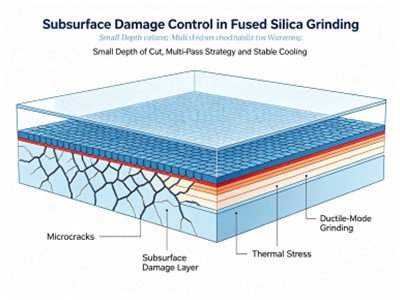
During grinding, material removal is dominated by brittle fracture mode:

  • Excessive grinding force easily induces micro‑cracks on workpiece surface;
  • Grinding heat cannot dissipate rapidly. Thermal stress may cause chipping, edge breakage or even cracking of components;
  • Cutting action of diamond grains generates subsurface damage layers. If such damage cannot be removed step‑by‑step in grinding phase, it will be inherited in polishing and degrade the performance of finished optical parts.

Therefore, the core grinding objective for fused silica: promote material removal toward ductile‑mode grinding. Adopt step‑down grit size strategy to control and eliminate subsurface damage layer progressively.
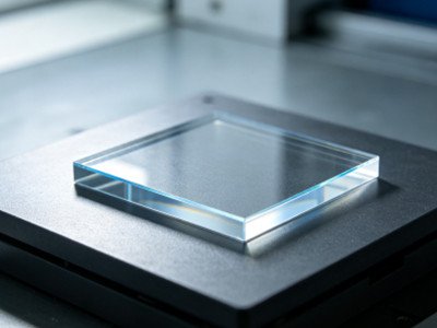
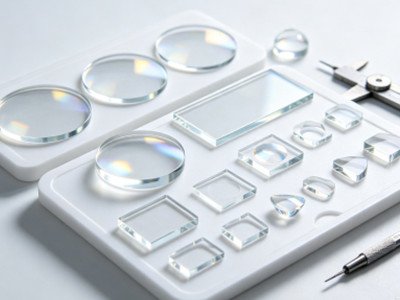
Fused Silica quartz glass 2

Graded Grinding Workflow and Key Parameters

Grinding of fused silica optical components strictly follows the principle of coarse‑to‑fine progressive processing. Each grinding step shall sufficiently remove subsurface damage and scratches left by the previous procedure. The dwell time for each step is recommended to be 2‑4 times of the time required to eliminate scratches from the prior process.

Complete process chain: Coarse Grinding → Semi‑Fine Grinding → Fine Grinding → Super‑Fine Grinding / Lapping → CeO₂ Polishing. Surface quality after polishing is evaluated according to MIL‑PRF‑13830B (Scratch‑Dig).

Process Flow: Coarse Grinding (Shaping) → Semi‑Fine Grinding → Fine Grinding → Super‑Fine Grinding / Lapping → Polishing
Process Principle: Remove subsurface damage from previous process step‑by‑step; reduce grit size progressively; dwell time of each stage is 2‑4 times the scratch‑removal time for former procedure.
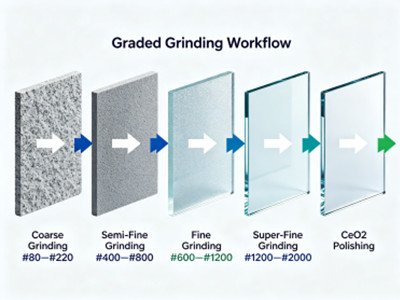
Fused Silica grinding work flow

Typical Process Parameters of Each Procedure

Procedure Recommended Grit Size Achievable Ra (μm) Core Function
Coarse Grinding #80‑#220 1.0‑3.0 Remove large stock allowance and realize basic shaping
Semi‑Fine Grinding #400‑#800 0.2‑0.5 Correct geometry and eliminate micro‑cracks generated in coarse grinding
Fine Grinding #600‑#1200 0.2‑0.4 Improve surface quality and reduce depth of damage layer
Super‑Fine Grinding / Lapping #1200‑#2000 0.05‑0.15 Pre‑polishing surface preparation, strictly control subsurface damage
Polishing CeO₂ Cerium‑oxide Polishing Slurry <0.5 nm Achieve optical‑grade ultra‑smooth surface
  • Coarse Grinding: Prioritize high material removal and shaping, trade partial surface quality for processing efficiency.
  • Semi‑Fine & Fine Grinding: Intermediate critical steps to suppress crack propagation and compress subsurface damage depth.
  • Super‑Fine Grinding: Pre‑treatment for polishing, reduce polishing stock removal and shorten polishing cycle.
  • Final Polishing: Obtain nano‑scale surface for optical applications.

Diamond Grinding Wheel Selection

Due to high hardness of fused silica, conventional silicon carbide or alumina wheels suffer fast wear and low removal efficiency. Diamond grinding wheels are mandatory for production. Synthetic diamond is the mainstream abrasive for fused silica processing for its uniform grit size, low impurity and controllable crystal morphology. Wheel selection shall cover five dimensions: abrasive type, bond, grit size, concentration and wheel hardness.

1 Bond Selection

  • Vitrified (Ceramic) Bond: For coarse and semi‑fine grinding. High rigidity, excellent chip removal performance and thermal stability, suitable for heavy stock removal.
  • Resin Bond: For fine grinding and super‑fine grinding. Good elasticity to reduce chipping risk and deliver fine finished surface texture.
  • Metal Bond: For scenarios requiring long service life and high‑precision form grinding of complex profiles.

2 Grit Matching (Mesh / European D‑Code Standard)

Grit size decreases progressively along processing stages. Reference for two grit standards:


Processing Stage Mesh Grit Size European D‑Code
Heavy‑stock Coarse Grinding #46‑#60 D46‑D64
Semi‑Fine Grinding #80‑#120 D20‑D30
Fine Grinding #180‑#240 D7‑D15
Pre‑polishing Super‑Fine Grinding #400‑#1000 and above D3‑D7

Note: European D‑Code denotes maximum grain dimension. Smaller D value means finer abrasive grain and lower surface roughness.

3 Wheel Concentration and Hardness

  • Concentration: 120%‑150% for heavy‑cut coarse grinding; 100% for general fine grinding; 75%‑100% for thin‑wall and high‑precision components.
  • Hardness Grade: Medium‑soft grade K, L, M is preferred to guarantee good wheel self‑sharpening performance, preventing burning and cracks caused by wheel dulling.

Key On‑Site Operation Guidelines

Process parameters directly determine final yield. Focus on peripheral speed, cutting depth, feeding strategy, cooling, wheel dressing and dynamic balancing:
  • Peripheral speed of grinding wheel: 25‑35 m/s.
  • Depth of cut by layers: 0.02‑0.05 mm per pass for coarse grinding; 0.005‑0.01 mm per pass for fine grinding.
  • Adopt small depth‑of‑cut multi‑pass strategy. Climb milling is preferred to lower chipping risk for brittle materials.
  • Sufficient cooling fluid shall be applied to dissipate grinding heat and avoid thermal‑stress cracking.
  • Perform regular wheel dressing and dynamic balancing to prevent scratches and waviness induced by vibration.

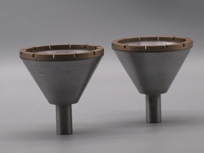
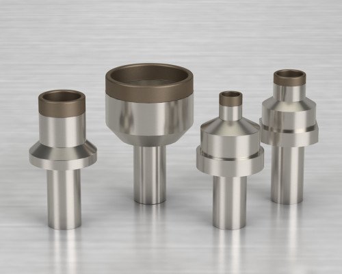
milling wheel for Fused Silica mounted grinding points for Fused Silica

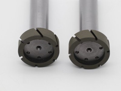
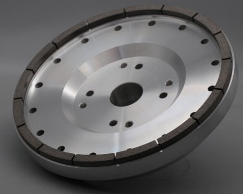
back grinding wheel for Fused Silica centerless grinding wheel for Fused Silica

Conclusion

Grinding of fused silica optical components is a systematic engineering combining grinding‑wheel selection, process design and parameter control. Key principles for practical production:
  • Diamond‑abrasive grinding wheels are required.
  • Decrease grit size step‑by‑step; select corresponding bond for different stages: vitrified bond for rough processing and resin bond for fine processing.
  • Apply multi‑pass small‑depth cutting and ensure adequate cooling.
  • Fully eliminate subsurface damage in each procedure; avoid carrying crack risks to subsequent steps.

surface damage in Fused Silica grinding

Proper implementation of above process can balance processing efficiency and surface quality, laying solid foundation for qualified optical‑grade surfaces in follow‑up polishing.
También podría ser de su interés
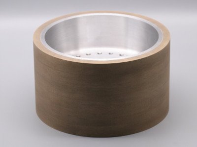
diamond milling grinding wheel

Diamond Milling Grinding Wheel for Optical Glass

Diamond milling wheel is used in the front stage of optical glass processing for rough grinding.Diamond milling grinding wheel is divided into flat and spherical diamond milling grinding wheel.The design of diamond grinding wheels enables them to adapt to various optical glass processing requirements. They usually use a high-hardness steel matrix to ensure sufficient strength and durability.
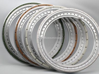
back grinding wheels

Diamond Back Grinding/Polishing Wheel for Optical Glass

Diamond back grinding wheel for machining optical glass with high efficiency and precision.Moresuperhard provide all kinds of diamond back grinding wheel for glass like metal diamond wheel,resin diamond wheel and vitrified diamond wheel.
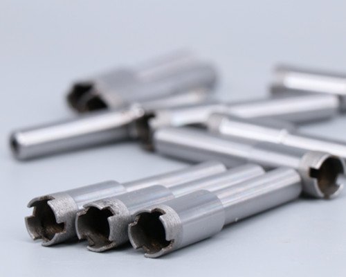
metal diamond drill bit

Diamond Drilling Tools for Optical Glass

Metal diamond drill bits are used for glass drilling, mainly for vertical and horizontal drilling machines. They are sharp and durable, and are produced according to international standards. They are widely praised by customers. They are widely used for drilling holes in high-grade optical glass and flat glass. They have the characteristics of high drilling accuracy, high speed and ultra-long service life.
tech@moresuperhard.com
008617700605088