Home > Industry Solutions > How to Eliminate Edge Chipping When Cutting Thick-Wall Quartz Glass Tubes (8–16 mm)

05

Nov

How to Eliminate Edge Chipping When Cutting Thick-Wall Quartz Glass Tubes (8–16 mm)

5
Share:

Quartz glass is a typical brittle material with Mohs hardness of 5.5‑6.5 and extremely low fracture toughness. Minor mechanical shock, vibration, thermal stress, or unsupported cutting‑exit surfaces will trigger edge chipping and subsurface micro‑cracks. For automatic cutting of large‑diameter thick‑wall quartz tubes (wall thickness 8‑16 mm), common defects include end‑face chipping, front‑and‑rear material breakout, exit‑edge spalling, and invisible micro‑cracks. These defects lead to mass rejection during subsequent cleaning, heat treatment and assembly, and severely reduce production yield across the quartz‑processing industry. Simply replacing cutting wheels rarely resolves recurring chipping, as defects arise from the combined effects of brittle‑material exit‑effect, vibration, thermal stress and improper cutting logic.
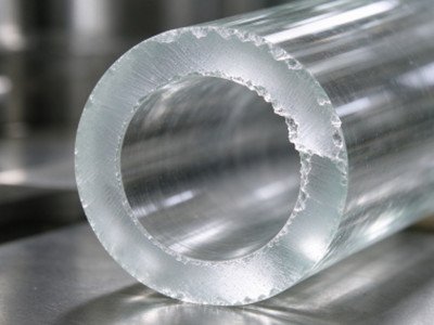
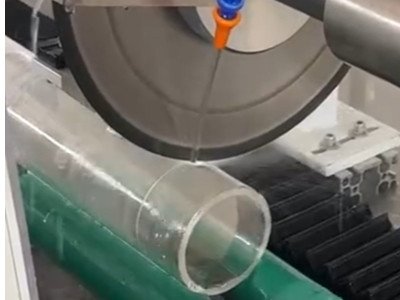
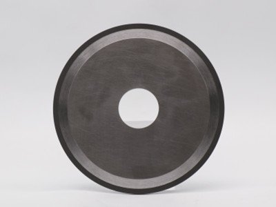
quartz galss tube quartz glass tube cutting

Root Causes of Chipping in Thick‑Wall Quartz Tube Cutting

  • Unsupported exit surface: Hollow quartz tubes have no backing support the moment the cutting wheel penetrates the rear wall. Diamond abrasive grains peel material away, and cracks propagate outward to form severe exit‑side chipping, the most frequent defect for 8‑16 mm wall‑thickness tubes.
  • Excessive vibration: High‑speed spindles running at 8000 RPM are sensitive to spindle run‑out, deformed flanges, wheel wobble, loose clamping and tube rotational jitter. Even micron‑level run‑out transforms gentle grinding into impact‑style hammering that shatters tube edges.
  • Concentrated cutting heat & insufficient cooling: Low thermal conductivity of quartz causes accumulated frictional heat during heavy‑stock‑removal thick‑wall cutting. Local temperature gradients induce thermal stress and micro‑cracks. Cooling fluid sprayed only onto the wheel surface fails to reach the cutting engagement zone; trapped swarf further scratches the cut edge.
  • Mismatched cutting‑wheel specifications: Metal‑bonded sintered wheels, coarse grit, large‑notched segmented wheels produce high cutting force. Over‑rigid overly‑thick wheels lack cushioning. Improper diamond grit size, concentration and bond formula amplify chipping risk.
  • Unreasonable feed logic: Constant‑speed feed through the full wall delivers maximum impact force at breakthrough. Over‑aggressive feed rates overload individual diamond grains and fracture quartz edges.
  • Residual stress in raw tubes: Poor annealing during quartz tube manufacturing leaves built‑in internal stress. Cutting disturbs stress distribution and triggers spontaneous crack propagation at kerf locations.

Industry baseline: Electroplated diamond wheels work reliably for thin‑wall tubes below 3 mm wall thickness. For wall thickness ≥8 mm, resin‑bonded diamond wheels represent the mainstream mature solution in domestic optical and semiconductor quartz processing.

Precise Cutting‑Wheel Selection (8000 RPM, Ø50‑60 mm wheel, tube wall 8‑16 mm)

Perimeter ProfileContinuous un‑notched rimReject corrugated or notched segmented rims; intermittent cutting creates periodic mechanical shock and increases chipping probability.

Parameter Item Recommended Specification Notes & Risk of Deviation
Bond Agent Resin bond Provides micro‑elastic cushioning, soft cutting action and restrains crack expansion; avoid metal‑sintered bond for thick‑wall applications.
Diamond Grit Size 240#‑320# Coarser than 200#: fast cutting yet heavy chipping and rough end face; finer than 400#: high cutting resistance, tool bogging and excessive heat, only for wall <3 mm.
Diamond Concentration 35%‑40% Excessive concentration causes grain crowding and poor self‑sharpening; low concentration raises single‑grain load and edge hammering.
Wheel Thickness 1.0‑1.4 mm Ultra‑thin wheels lose rigidity and wobble at 8000 RPM; select thinnest wheel while maintaining sufficient structural stiffness.
Diamond Grade High‑strength monocrystalline diamond with good self‑sharpening performance Low‑fracture‑toughness fragmented diamond fractures prematurely and shifts material removal into destructive friction‑dominated rubbing.
Mounting Flange Flange parallelism ≤0.005 mm; flange diameter ≥1/3 of wheel outer diameter Even clamping pressure suppresses high‑speed wheel run‑out.

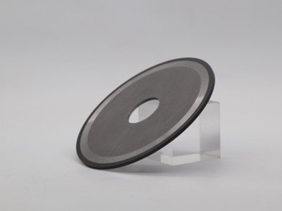
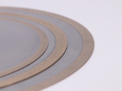
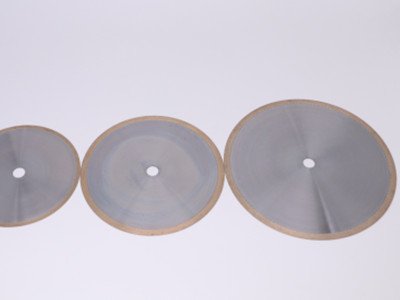
resin diamond cut off wheel resin diamond disc for quartz

Cutting‑Process Parameter Optimization

With spindle speed fixed at 8000 RPM, modifying feed strategy delivers fast low‑cost improvement against chipping defects.

Segmented Variable‑Speed Feeding (Core Process for Exit‑Side Chipping Control)

Do not cut through the wall using constant‑speed single‑pass feed:

  1. Entry segment: Low feed rate to mitigate impact when wheel first contacts tube wall.
  2. Mid‑cut segment: Maintain stable moderate feed rate.
  3. Exit breakthrough segment: Reduce feed speed by ≥50 % when residual wall thickness reaches 1‑2 mm. This lowers impact at penetration and allows stress‑crack relaxation, an established industry practice for thick‑wall quartz.

Reference overall feed range for resin‑bond wheels: 30‑60 mm/min. Reduce feed rate when chipping persists before attempting wheel replacement.

Wet‑Cutting Mandatory; Dry‑Cutting Prohibited

Dry cutting generates extreme thermal stress and unavoidable hidden micro‑cracks. Use filtered pure water plus small‑dose neutral rust inhibitor for coolant. Oil‑containing cutting fluids are forbidden as residues penetrate micro‑cracks. Deploy dual‑nozzle layout: one aimed at cutting entry zone, the second directed at the rear exit engagement zone. Coolant must directly impinge the kerf interface and flush quartz dust to prevent secondary scratch damage from trapped swarf.

Periodic Wheel Dressing

Resin‑bond wheels develop resin glazing and passivated diamond grains in service. Cutting transitions from abrasive removal to compressive rubbing, which re‑introduces chipping. Dress wheels periodically with white‑alumina dressing blocks to expose fresh sharp diamond abrasive points.

Work‑Holding and Anti‑Chipping Backing‑Support Solutions

Hollow tubing fundamentally differs from solid rod stock: the rear kerf position is unsupported during penetration.

Clamping Requirements

Adopt fully‑enclosed soft‑gum V‑blocks lined with rubber or polyurethane to distribute clamping force; avoid direct hard‑metal contact with quartz surfaces. For rotary automatic cutting, control tube rotational run‑out within 0.02 mm, as rotational jitter provides continuous impact excitation source.
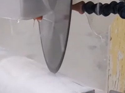
150 diamond cut off wheel cutting thick wall quartz glass

 Exit‑Side Backing‑Support Comparison

Solution Description Applicable Scenario & Effect
A: Retractable inner mandrel backing (Mass‑production preferred) Mandrel inserts inside quartz tube and provides rigid backing behind cutting position at breakthrough moment to suppress outward crack propagation. Largest chipping‑reduction improvement; mainstream solution for automated thick‑wall quartz tube cutting lines.
B: Sacrificial backup plate (Simple retro‑fit) Place disposable sacrificial plate externally at cutting station; allow slight wheel penetration into plate material to eliminate unsupported breakthrough condition. For small‑batch production where internal mandrel modification is mechanically impractical.

Raw‑Material Pre‑Screening

Select adequately‑annealed incoming quartz tubes. Reject raw stock with surface scratches or pre‑existing cracks, because pre‑existing flaws propagate and enlarge during cutting operations.

On‑Site Troubleshooting Checklist

Observed Defect Symptom Priority Inspection Items
Chipping concentrated at exit‑breakthrough location Add internal backing mandrel; activate exit‑segment feed deceleration.
Uniform multi‑sided chipping plus rough end‑face texture Wheel glazing / blunt grit; excessive coarse grit; insufficient cooling performance.
Intermittent non‑reproducible chipping (good and bad parts mixed) Spindle run‑out, flange flatness, wheel wobble, tube rotary concentricity.
Hair‑line micro‑cracks visible at kerf Excessive thermal stress; insufficient coolant flow; overly‑aggressive feed velocity.

Common Industry Misconceptions

  • Myth 1: Sharper wheels always equal better results. Coarse‑grit or metal‑sintered wheels deliver aggressive cutting impact and raise chipping risk for thick‑wall quartz.
  • Myth 2: Boost feed rate to raise throughput. Brittle‑material removal has strict feed‑rate upper limits. Yield loss from chipping and hidden micro‑cracks far outweigh minor cycle‑time savings.
  • Myth 3: Any water spray qualifies as adequate cooling. Coolant only hitting the front wheel surface leaves exit‑rear kerf overheated and swarf trapped.
  • Myth 4: Consume cutting wheels until full wear‑out. Glazed resin wheels keep rotating but shift from cutting to squeezing, generating invisible subsurface damage without obvious visual warning.

Step‑By‑Step Implementation Priority

  1. Modify CNC program logic: implement feed deceleration for exit breakthrough zone; re‑orient coolant nozzles to target exit‑rear cutting zone.
  2. Deploy correctly‑specified resin‑bond diamond cutting wheel: 240#‑320# grit, 35‑40 % concentration, continuous un‑notched rim, 1.0‑1.4 mm thickness.
  3. Install retractable internal backing mandrel for exit‑side mechanical support.
  4. Build periodic inspection workflow: measure spindle run‑out and flange parallelism; maintain logs for wheel dressing and replacement cycles.

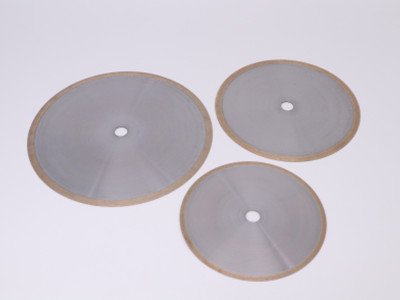
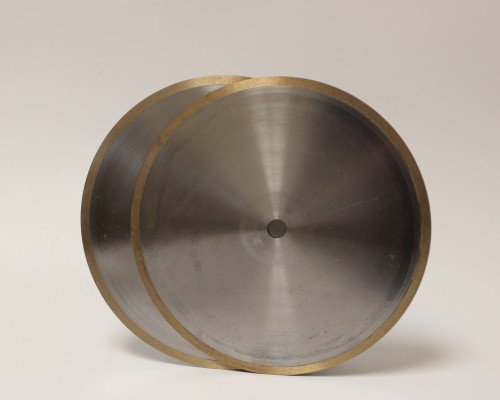
metal diamond cut off wheel diamond cutting disc for quartz tubes

Frequently Asked Questions

Q: Why does chipping still occur after I change to new cutting wheels?
A: Chipping for thick‑wall quartz is multi‑factor driven. Unsupported exit geometry, vibration, thermal stress or inappropriate feed parameters will produce defects even with brand‑new wheels.
Q: Can I use metal‑bond diamond wheels for 12 mm wall‑thickness quartz tubes?
A: Not recommended for high‑yield requirements. Metal‑bond wheels deliver high rigidity and cutting impact and typically create heavy edge breakout on thick brittle quartz.
Q: How much should feed speed drop for the exit‑breakthrough segment?
A: Reduce feed by minimum 50 % when residual wall thickness reaches 1‑2 mm as the wheel approaches breakthrough.
Q: Is an internal mandrel mandatory for solving exit‑side chipping?
A: Mandrels give the largest yield improvement for mass‑production lines. Small‑batch workshops can start with sacrificial backup plates as a lower‑cost alternative.
Q: What causes invisible subsurface micro‑cracks without visible chipping?
A: Over‑fast feed, glazed blunt cutting wheels, inadequate cooling and excessive vibration generate subsurface damage with no obvious surface breakout, leading to late‑stage part failure during thermal processing or assembly.
También podría ser de su interés
metal sintered diamond blades

Diamond Cutting Blade for Borosilicate Glass

Professional diamond cutting blades with resin and metal bonded designs are specially engineered for precise, chip-free cutting and grooving of borosilicate glass tubes, quartz tubes and industrial glass pipelines, delivering high precision, smooth edge finish and long service life for diverse industrial precision processing needs.
tech@moresuperhard.com
008617700605088